Because of the situations mentioned above, setting up measurement is almost always necessary for these inverters. Therefore, the manufacturer includes current transformer clamps in the package. Each of the three phases uses two wires for measurement, meaning the CT-based measurement requires six conductors in total.
From the bottom view of the inverter, the connector highlighted in red is the one referred to in this article.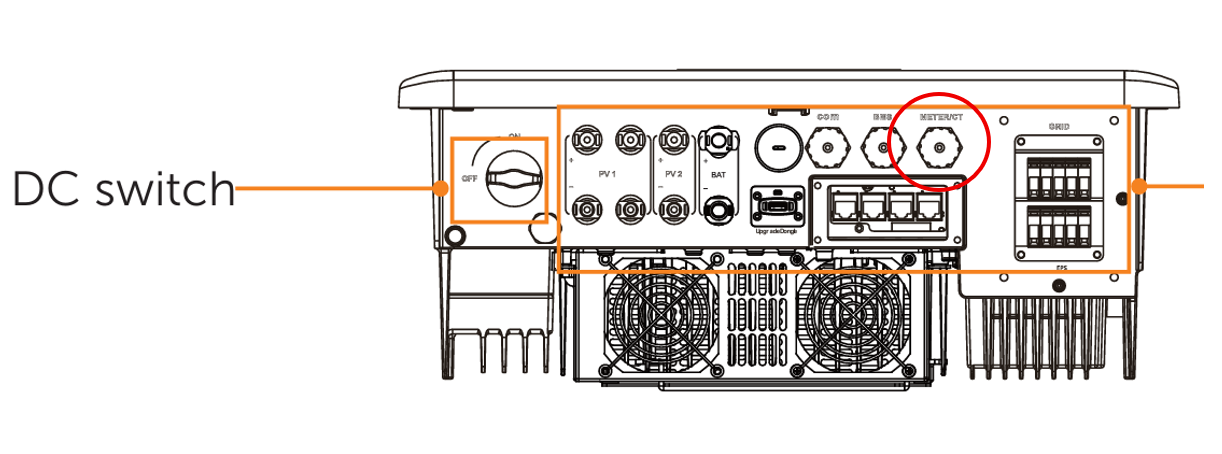
SolaX supplies three CT clamps already connected to a plug head, from which you must extend a communication cable with RJ45 connectors at both ends. One end connects to the inverter’s CT/Meter port, and the other to the RJ45 ends of the CT clamps. Since this creates a male-to-male connection, the manufacturer provides a female-to-female adapter with the communication cable.
In the User Manual, there is a table showing the pin layout of this port: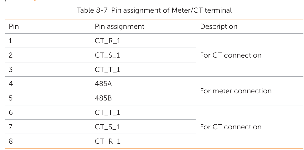
- Pins 4–5 are reserved for the smart meter.
- Pins 1–3 and 6–8 correspond to the CT clamps.
Thus, if you only intend to use a meter, you only need to connect two pins in the communication cable. For CT clamps, six pins are required. However, by connecting both CT clamps and the meter, you can create two separate measurement points.